Creates a base view from model space or Autodesk Inventor models.
List of Options
The following options are displayed.
Select
- Model Space Selection
Switches to the model space to select solids and surfaces to use in the layout.
- Return To Layout
Switches to the layout containing the drawing view.
Representation Panel
This panel is visible only when you create a base view from an Inventor model. Representation types are model specific. Some of the options may not be available in the selected model.
- Design View
Specifies the assembly design view representation to show in the base view being created.
This option is available only if the selected model is an Inventor assembly (*.iam) that contains design view representations. It is also not available during the creation of projected views.
- Positional Representation
Specifies the positional representation to show in the base view being created.
This option is available only if you are creating a base view from an Inventor assembly (*.iam) that contains positional representations. It is also not available during the creation of projected views.
- Level of detail
Specifies the level of detail representation to show in the base view.
This option is available only if the selected model is an Inventor assembly (*.iam). It is also not available during the creation of projected views.
- Weldment
Specifies the weldment state to show in the base view. The list does not explicitly show the preparatory state. Instead, it displays the names of the components in the pre-welding preparatory state.
This option is available only if the selected model is an Inventor weldment assembly (*.iam).
- Member
Specifies which member from an iAssembly factory or iPart factory to show in the base view.
This option is available only if the selected model is an iAssembly factory or an iPart factory (*.iam, *.ipt).
- Sheet metal
Specifies the sheet metal view to show in the base view.
This option is available only if the selected model is an Inventor sheet metal file (*.ipt).
- Presentation
Specifies the presentation view to show in the base view.
This option is available only if the selected model is an Inventor Presentation document (*.ipn).
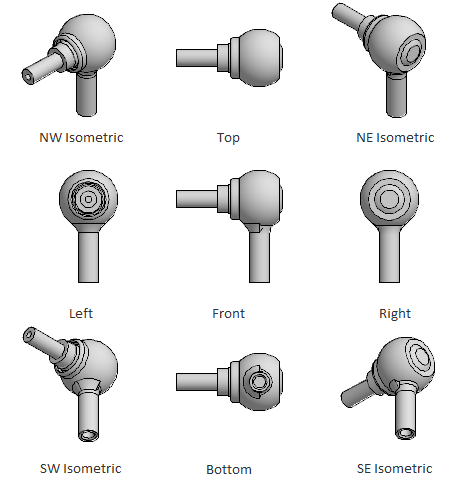
Orientation Panel
- Orientation
Specifies the orientation to use for the base view being created. This option is available only during the creation of base views.
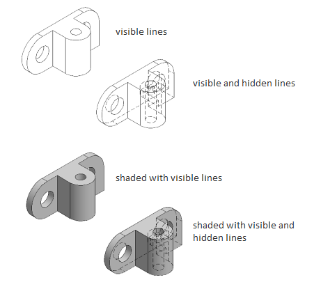
Appearance Panel
- Hidden Lines
Specifies the display style to use for the selected view.
- Scale
Specifies the scale to use for the view.
- Edge Visibility
Displays a list of objects to show in the selected view.
- Interference edges. Displays a line to show where two intersecting solid bodies meet.
- Tangent edges. Displays a line to show smooth edges formed by surfaces intersecting tangentially.
- Foreshortened. Shortens the length of tangential edges to differentiate them from visible edges.
- Bend extents. Displays sheet metal bend extent lines. Sheet metal bend extent lines indicate the location of transition about which a bend hinges or folds, in a flattened sheet metal representation.
- Thread features. Displays thread lines on screws and tapped holes.
- Presentation trails. Displays the lines (in drawing views from exploded views) that show the direction along which a components are moved into assembled position.
- Cut Inheritance
Specifies if the view created out of a section view inherits the section cut. This option is disabled in this view.
- View Options
Displays the View Options dialog box. This dialog box specifies how to anchor the base view being created, and how to display Inventor Reference Parts.
Modify Panel
- Move
Moves the base view being created, after it is placed in the drawing area, without forcing you exit the command.
Create Panel
- OK
Completes the view creation process and closes the Drawing View Creation Ribbon Contextual Tab.
- Cancel
Exits the view creation process and closes the Drawing View Creation Ribbon Contextual Tab.