You can specify clipping boundaries to display a limited portion of an external reference drawing or block reference.
You can clip external references such as DGN, DWF, IMAGE, PDF underlays, or block references. With a clipping boundary, you can determine the portions of an external reference or block reference that you want to display by hiding the redundant parts of the reference inside or outside the boundary.
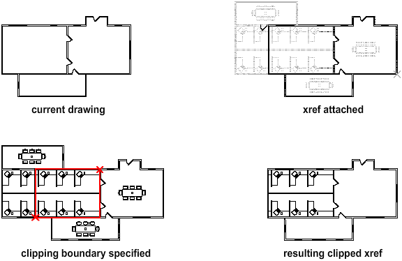
You can control the display of the clipping boundary with a clipping frame. The clipping system variable for XREF, PDF, DGN, DWG, and IMAGE underlays are XCLIPFRAME, PDFFRAME, DGNFRAME, DWFFRAME, and IMAGEFRAME respectively.
The clipping boundary can be a polyline, rectangle, or a polygon with vertices within the boundaries of the image. You can change the boundary of a clipped image. When you clip a boundary, the objects in the external reference or block are not altered; only their display is changed.
With the XCLIP, DGNCLIP, DWFCLIP, PDFCLIP, and IMAGECLIP commands, you can control the following viewing options:
Editing Options
After an external reference or block reference has been clipped, it can be moved, copied, or rotated just like an unclipped external reference or block reference. The clipping boundary moves with the reference. If an xref contains nested clipped xrefs, they appear clipped in the drawing. If the parent xref is clipped, the nested xrefs are also clipped.
Resize Clipping Boundaries
If you want to change the shape or size of a clipping boundary for external references and block references, you can use grips to edit the vertices just as you edit any object with grips.
In case of rectangular grip editing, you can maintain the closed four-sided rectangle or square shape of the rectangular clipping boundary because two vertices of the same side of the rectangular clipping boundary are edited together.
Limitations for Clipping Boundaries
When clipping an referenced drawing or block the following limitations apply:
- A clipping boundary can be specified anywhere in 3D space, but it is always applied planar to the current UCS.
- If a polyline is selected, the clipping boundary is applied in the plane of that polyline.
- Images in external references or blocks are always clipped within the rectangular extents of the reference. When you apply polygonal clipping to images in externally referenced drawings, the clipping boundary is applied to the rectangular extents of the polygonal boundary, rather than to the polygon itself.